Project in Mechatronics · UCLouvain · Eurobot 2019 · Team of 6
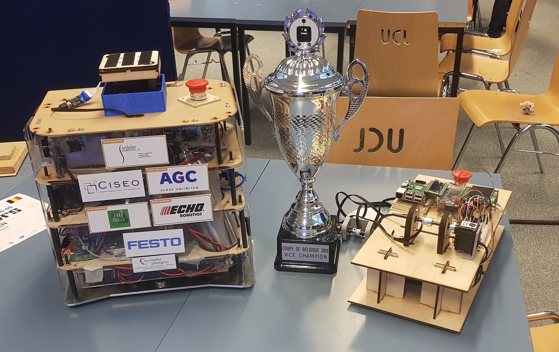
Fully autonomous robot built for the Eurobot international robotics contest. Implemented path planning, Kalman-filtered LIDAR localisation, low-level wheel control, and an Android remote — running on a Raspberry Pi coupled to an FPGA. Finished 2nd in Belgium and qualified for the European finals.
6Team membersMaster in electromechanical engineering
3Compute layersRaspberry Pi · FPGA · Android
2019Eurobot themeAtom Factory — hockey pucks scoring
Context
Eurobot 2019 — Atom Factory
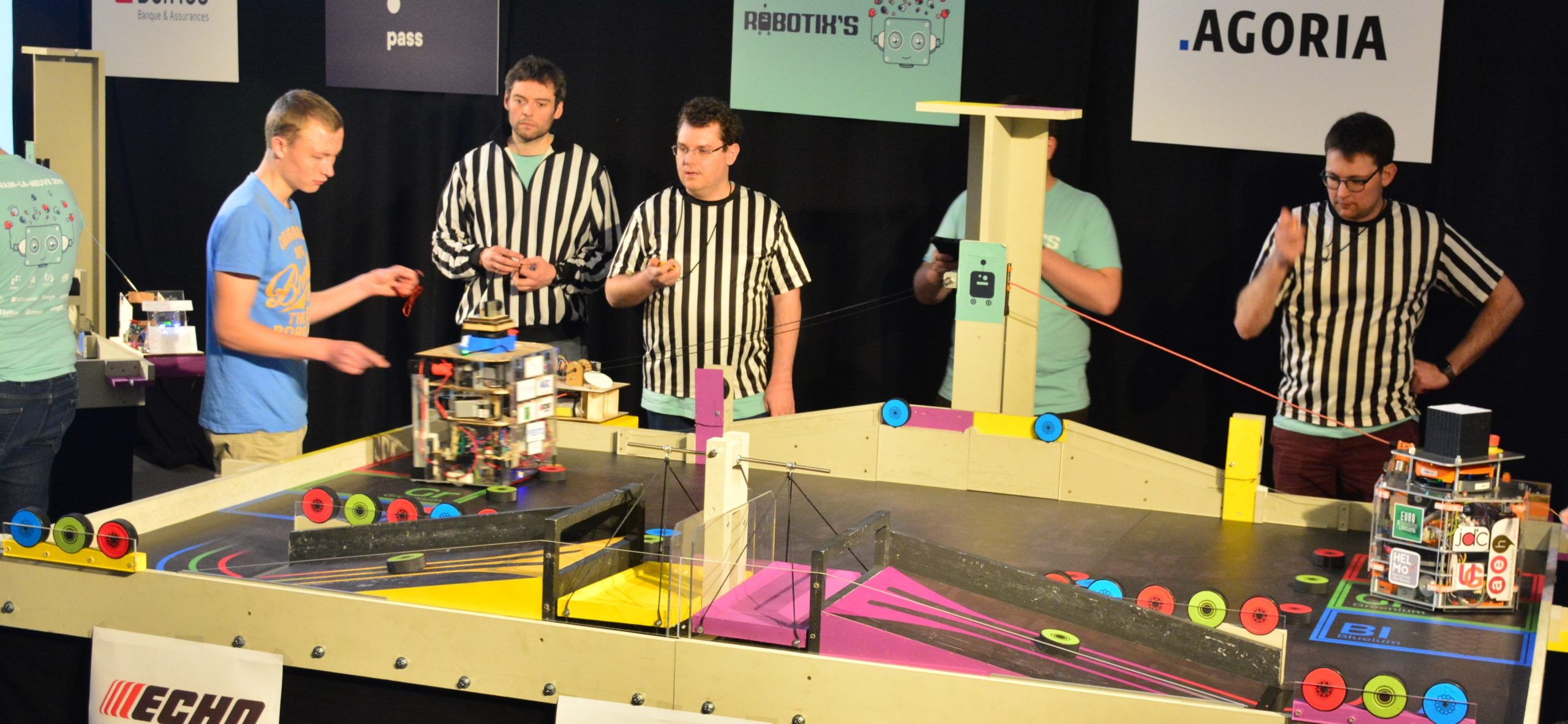
Eurobot is a French international robotics contest gathering the best European student teams. The 2019 edition required autonomous robots to score points by moving hockey pucks (atoms) onto a weighing scale, an accelerator, or the robot's starting zone — within a fully autonomous two-minute match.
🏁
Robotix's (Belgium)
The Belgian qualifier determining which teams advance to the European finals. Our team placed 2nd nationally and 1st within UCLouvain, earning a slot at the international contest.
🤖
Fully autonomous
The robot operated without any human control during the match. It navigated, localized itself, avoided obstacles, and executed token-moving actions entirely on its own.
⚙️
Robot approval
Before competing, each robot must pass a technical inspection verifying compliance with size, weight, and safety constraints. Our robot cleared approval on the first attempt.
Software
Algorithms & control systems
🗺️Path Planning — Potential Fields
▸Robot is repelled from obstacles and attracted to the target position via artificial potential fields.
▸Gradient descent on the combined potential surface produces smooth, collision-free trajectories.
▸Handles dynamic obstacles: newly detected objects update the repulsion field in real time.
📍Localisation — Kalman Filter
▸Wheel odometry provides a continuous position prediction between sensor updates.
▸RPLIDAR A2 (high-frequency rotating LIDAR) provides absolute position measurements against the known map.
▸Extended Kalman filter fuses both sources: odometry predicts, LIDAR corrects — robust to wheel slip and sparse scans.
🔌Low-Level Wheel Control
▸Analyzed motor dynamics to model the voltage–speed transfer function for each drive wheel.
▸Tuned a PID controller minimising the error between commanded and measured wheel velocity.
▸Implemented on the FPGA in SystemVerilog for deterministic, low-latency PWM generation.
📱Android Remote — Wi-Fi
▸Custom Android app communicating with the robot over a Wi-Fi socket.
▸Supports manual robot control, live sensor readings, and remote actuation of mechanisms.
▸Used during development and pre-match testing; disabled during autonomous competition runs.
Hardware
Compute & electronics stack
The robot is organized as a three-layer compute hierarchy: high-level reasoning on Linux, real-time I/O on the FPGA, and wireless oversight via Android. Mechanics and PCBs were designed and manufactured by the team.
LAYER 3
Android ApplicationWi-Fi remote control and telemetry. Receives sensor data and sends motion commands over a TCP socket. Built for development and pre-match calibration.
LAYER 2
Raspberry Pi (Linux · C++)Main compute unit running the path planner, Kalman filter, and high-level state machine. Sends velocity setpoints to the FPGA over GPIO/SPI.
LAYER 1
FPGA — DE0-NANO (SystemVerilog)Real-time I/O layer. Handles PWM generation for motor drivers, encoder reading, and sensor interfacing with deterministic timing the Linux kernel cannot guarantee.
SENSOR
RPLIDAR A2High-frequency rotating LIDAR providing 360° distance measurements. Used as the absolute localisation reference for the Kalman filter.
🔩Mechanical Design
▸Full robot modeled in SolidWorks (CAD) before fabrication.
▸Electropneumatic architecture designed for the token-grasping mechanism.
▸Mechanical parts machined and 3D-printed in-house by the team.
⚡Electronics & PCBs
▸Electrical schematics designed from scratch covering power, motor drivers, and sensor wiring.
▸PCBs synthesized in Eagle and manufactured for the motor control and sensor boards.
▸Power distribution designed to handle peak motor current draw during acceleration.
Dynamics & Sizing
Robot dynamics analysis
Before any code was written, the robot's physical constraints were derived analytically — sizing the motors, gearboxes, wheels, and structural elements to meet the contest's acceleration, speed, and payload requirements.
Motors
Sized to deliver sufficient torque for the required acceleration profile given the robot mass and wheel radius.
Gearboxes
Reduction ratio chosen to balance top speed against torque, staying within the motor's efficient operating range.
Wheels
Diameter and material selected for traction on the contest surface without exceeding the footprint constraint.
Structure
Load path analyzed to keep the frame rigid under the inertial loads of fast direction changes during the match.